

 LC1D80BD↓ 1% off MRP1 / 6

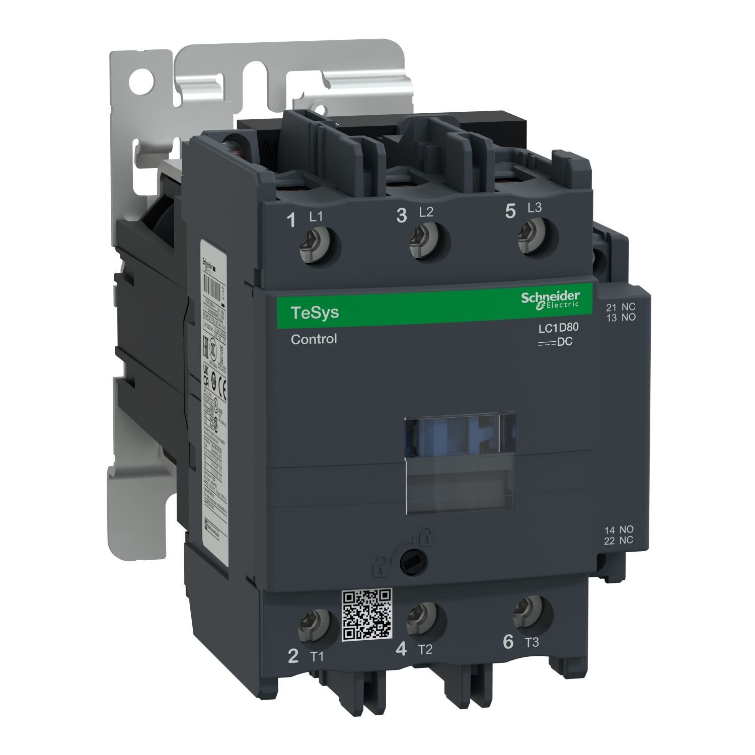
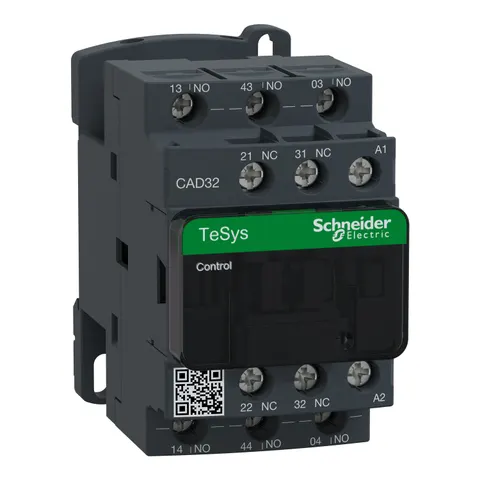
Schneider TeSys LC1D Power Contactor · 3P · 125 A AC-3 · 1 NO + 1 NC aux · 24 V DC coil
- Secured by Razorpay · UPI, cards, net banking, wallets
- GST invoice with every order
- Tracked delivery, 3 to 7 working days
Schneider TeSys LC1D Power Contactor · 3P · 125 A AC-3 · 1 NO + 1 NC aux · 24 V DC coil: Elume price today ₹50,478 per pc incl. GST, 1% below the ₹50,988 MRP. The price has held steady for the last 30 days.
TeSys Deca contactor, 3 poles (3NO), for motor control applications up to 80A/1000V AC-3/AC-3e (37kW@400V). It provides a 24V DC coil, 1NO+1NC built-in auxiliary contacts (NC mirror certified), power connection by screw terminals, control connection by screw clamp terminals. For operating rates until 3600 cycles/hour and environments until 60°C, it procures high reliability and durability. Compact (85mm width), DIN-rail mounting or screw fixing. Multi-standards certified (IEC, UL, CSA, CCC, EAC, Marine), Green Premium compliant (RoHs/Reach).
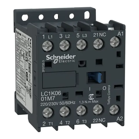
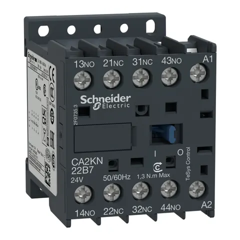
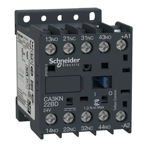
Is Schneider TeSys LC1D Power Contactor · 3P · 125 A AC-3 · 1 NO + 1 NC aux · 24 V DC coil genuine and warranty-backed?
Yes. Every Schneider product on Elume is 100% genuine, sourced through authorised channels, and carries the manufacturer's standard warranty.
Do you deliver across India?
Yes. We deliver anywhere in India our couriers serve, usually within 3 to 7 working days from order confirmation. The delivery charge follows the order value (the GST-inclusive goods total after any discount code): ₹200 under ₹2,000; ₹100 from ₹2,000 to under ₹4,000; free from ₹4,000 to ₹25,000; ₹1,000 above ₹25,000, because large orders ship insured, often in several boxes. Heavy consignments add ₹1,000 for every started 10 kg beyond the first 10 kg of the order's total shipping weight, even when delivery is free. A free-delivery code makes the whole delivery charge zero. Every charge is shown at checkout before you pay.
Can I get a GST invoice?
Yes, on orders delivered in India. Enter your GSTIN at checkout and we issue a GST invoice with tax shown separately, so businesses can claim input tax credit.
Is there a wholesale or bulk rate?
Yes. Orders of 15 or more pcs get a wholesale rate about 5% below the listed Elume price, shown on every product page.
What if I find it cheaper somewhere else?
Tell us. If the same Schneider product is listed for less, GST and delivery included, by an authorised Indian online seller, we match that price, before you order or within 7 days of ordering. The terms are on our lowest-price guarantee page.
What is the return policy?
For delivery in India, unused items in original packaging can be returned within 7 days of delivery, with free return shipping.